SyDPy short tutorial
This tutorial comprises several examples written for SyDPy with explanations:
Designing the D Flip Flop (DFF)
First, let’s take a more traditional approach, using the signals only. Whole example can be found in the examples/dff/dff.py.
# Every SyDPy module is a subclass of the Module
class Dff(Module):
    # Mark a member function as a Module architecture
    @arch_def
    def rtl(self,

            clk : sig(bit).slave,
            din : sig(bit).slave,
            dout: sig(bit).master
            ):

        # A process sensitive to a rising edge of the clk
        @always(self, clk.e.posedge)
        def reg():
            # On every rising edge of the clk we pass din to dout
            dout.next = din
Every module in SyDPy is implemented as a class derived from the Module SyDPy class. The implementation of a module is contained within one or more architectures. The architectures are member functions marked by an @arch_def or @arch decorator. Only one architecture per class can be marked with @arch_def decorator, making it the default architecture when the module is instantiated.
The parameter list of an architecture (besides the self parameter) contains the interfaces (a.k.a ports in other HDL) and configuration declaration of the module. In Dff example, we only have the declaration of 3 interfaces: clk, din and dout. Using annotations we specify which interfaces will be used to communicate with outside world. In this example, the interface below has the following elements:
sig(bit).slave
| sig | The interface will be of the type sig, which behaves the same as the signal or logic types of HDL languages. |
| bit | The data type of the interface will be a bit vector of a width 1 (a single bit of data). |
| slave | The module will receive the data via this interface. |
In order to transfer data from the input to output (synchronous to the clk), we declare a process:
@always(self, clk.e.posedge)
def reg():
    dout.next = din
The @always decorator creates the process out of the function, which means two things:
- It assigns a sensitivity list to the function
- It registers the function with the simulator
Sensitivity list consists of a list of events that will, when triggered, have the simulator call a process. The most commonly encountered events are:
| changed | Event will trigger whenever a value changes (newly written value is different than the old one). |
| updated | Event will trigger whenever a new value is written (newly written value can be same as the old one) . |
| posedge | Event will trigger whenever a value changes from False to True. Value need not be of boolean type, but has to be evaluable to the boolean type. |
| negedge | Event will trigger whenever a value changes from True to False. Value need not be of boolean type, but has to be evaluable to the boolean type. |
We acheived the following:
Whenever the value read via clk interface changes from False to True, the value read from din interface will be transferred to dout interface, which describes a DFF exactly.
Verification environment for DFF
In order to simulate the design, we need to supply some stimuli and examine the output. The testbench module might look like this:
class TestDff(Module):
    @arch_def
    def dflt(self):
        self.inst(Clocking, clk_o='clk', period=10)

        self.inst(Dff, clk='clk', din='din', dout='dout')

        self.inst(BasicRndSeq, seq_o='din', delay=30, intfs={'seq_o' : tlm(bit).master})
The default architecture of the testbench module instantiates 3 submodules:
- Clocking module that outputs a clock with desired period. Clocking is a helper module contained with SyDPy, yet it is a standard SyDPy module and the code can be viewed in sydpy/procs/clk.py.
- Dff module that we declared above
- BasicRndSeq module for random data generation.
To instantiate a submodule, the inst member function of the SyDPy Module class is used. This function performs the following:
- Instantiates the module passed as the first argument.
- Registers the instantiated module as a submodule, thus creating the module hierarchy.
- Passes the remaining arguments to the Module architecture.
The module interfaces (ports) are connected via channels. Channels are referenced by their names using strings. Therefore, when interface is assigned a string, it will connect to the channel of the same name. SyDPy automatically manages the creation of the channels.
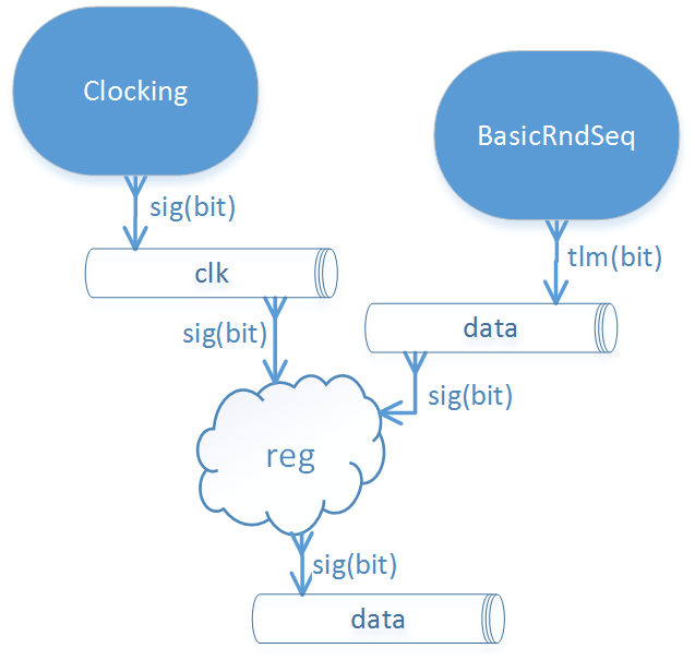
The dataflow of DFF testbench.
Notice how the channel din is written to using the transaction level interface (tlm), and read from using the signal interface (sig). This is a powerful feature of SyDPy channels which allows better decoupling between the modules. The information can be written to channel using one interface and read out using multiple other interfaces. SyDPy channels do all the conversions internally.
We acheived the following:
- We will have a steady clock with 10 ticks period fed into our DFF module via clk channel.
- We will have a sequence of random bits fed into our DFF module via din channel.
Simulating the design
We need to form a configuration dictionary to properly setup the simulator. The minimum we have to supply is:
conf = {
        'sys.top'           : TestDff,
        'sys.extensions'    : [VCDTracer],
        }
By supplying this configuration to the simulator, we inform it that the top module for simulation is TestDFF, and that we would like to use a simulator extension: VCDTracer for creating VCD waveform from the simulation.
We can now run the simulation using:
.. code:: python
Simulator(conf).run()
The out folder will be created in the folder where the TestDFF python module is located. Within the folder, the sydpy.vcd file contains the waveform which can be viewed by any VCD viewer (GTKWave for an example):
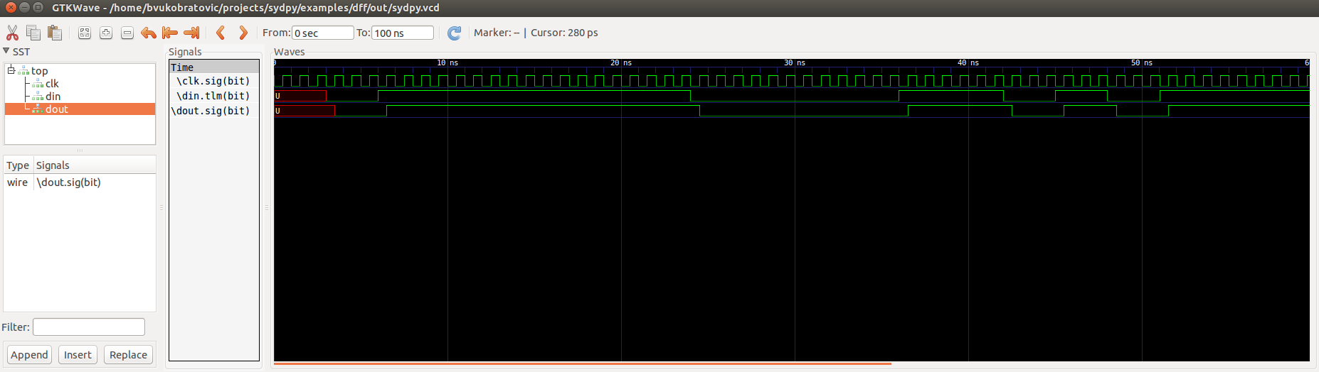
The VCD waveform of DFF testbench viewed by GTKWave.
DFF using seq interface
SyDPy supports the seq interface for exchange of information synchronous to some clock. We can thus use it to implement a data flip-flop. Whole example can be found in the examples/dff/dff1.py.
class Dff(Module):
    @arch_def
    def rtl(self,
            clk: sig(bit),
            din: seq(bit),
            dout: sig(bit).master
            ):

        din.clk <<= clk
        dout <<= din
First, let’s notice a couple of new things:
- The slave attribute has been removed from the interface declarations. Without any attribute, the slave side of the interface is implied.
- The opperator <<= is used to connect the interfaces without using the process.
The din interface is now declared to be of seq type. This means that din expects to receive data synchronous to the clock. Which clock then? Well we have to apply one. This is done by connecting the clk subinterface to desired clock:
din.clk <<= clk
We internally connected din to dout. Since these interfaces are of different type, SyDPy will again perform the conversion internally, i.e. dout will be updated with the din data sampled at the moments of clk rising edges.
Verification environment for new DFF
Here we see the true power of SyDPY channels and interfaces. There is no need to change anything in our testbench. We will only be reading from the din channel via different interface, and SyDPy will handle the conversion process. The dataflow remains similar:
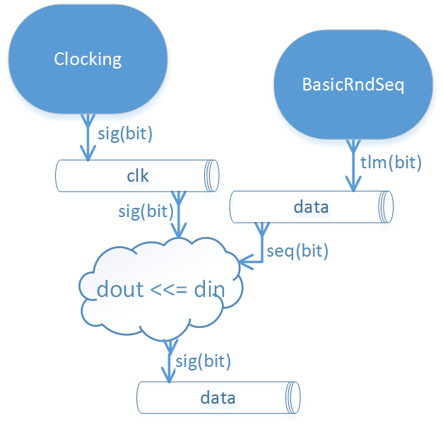
The dataflow of DFF testbench.
Simulating the design
Upon running the simulation we see that the resulting waveform of the dout channel reveals the same functionality. However, we see that the din interface is no longer simple, but consists of several subinterfaces: clk, data and handshaking subinterfaces valid and last.
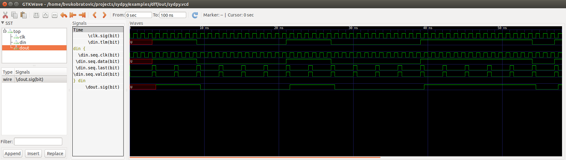
The VCD waveform of DFF testbench viewed by GTKWave.
Johnson counter example
Let’s now introduce some more SyDPy features by designing the Johnson counter. Whole example can be found in the examples/johnson/johnson.py.
class Johnson(Module):
    @arch_def
    def rtl(self,

            clk : sig(bit),
            dout: 'seq(Bit(N)).master',

            N=1
            ):

        dout.data.init(0)
        dout.clk <<= clk
        dout.data <<= dout[N-2:0] % (~dout[N-1])
First we should note that we are implementing an arbitrary width counter. The bit width is supplied via parameter N to the architecture.
Notice then, that the interface type for dout is given using string, which has to be done whenever a parameter is used to define the type.
dout: 'seq(Bit(N)).master'
The reason why we needed the string instead of simple instantiation as before, lays in the innerworkings of Python which evaluates the function annotations before the value of the parameter N is known. SyDPy overcomes this by using strings, and evaluating them only after the parameter values are known.
The module has single data interface dout of type seq. In previous example, we have seen how the reading via seq type interface behaves. In this example, we can see how writing via seq type interface is done via its data subinterface:
dout.data <<= dout[N-2:0] % (~dout[N-1])
The data subinterface is of type sig with the same data type as its parent seq type interface, i.e. sig(Bit(N)) in this example. Here we are connecting an expression (dout[N-2:0] % (~dout[N-1])) to dout.data. Please note the following:
- Operator [] is used for slicing. When interface is sliced, all the data read from it, are first sliced and then introduced into the expression.
- All interfaces contained within the expression are first converted (internally by SyDPy) to the resulting interface type. This means that all the data read via dout interface of type seq, is first converted to sig interface type. Therefore, when the expression is evaluated, the sampled (by the dout clock) data is read via dout.
- Operator % is produces bit string concatenation.
Note: By writing via seq type interface and reading via sig type interface, functionality equivalent to the hardware register is achieved
Verification environment for Johnson counter
The following code can be used to simulate the Johnson module we implemented:
class TestJohnson(Module):
    @arch_def
    def dflt(self, cnt_n=1):
        self.inst(Clocking, clk_o='clk', period=10)

        self.inst(BasicRndSeq, seq_o='cnt_en', delay=50, init=0, intfs={'seq_o' : tlm(bit).master})

        self.inst(Johnson, clk='clk', dout='cnt_out', N=cnt_n)

        cnt_out = self.seq(Bit(cnt_n), slave='cnt_out', clk='clk')
        cnt_out.ready <<= 'cnt_en'

conf = {
    'sys.top'           : TestJohnson,
    'sys.extensions'    : [VCDTracer],
    '/top.cnt_n'        : 4
    }

Simulator(conf).run()
The dataflow of the testbench is given in figure below:
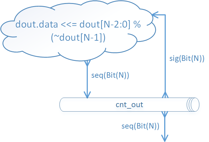
The dataflow of Johnson counter testbench, without subinterfaces shown.
Notice the member function seq of the Module class that can be used for more compact instantiation of an interface of type seq. Similarly, the Module class has the sig and tlm member functions.
So, the Johnson module is writing the counter values to the cnt_out channel via seq type interface. In order to generate a new counter value, the “old” value is read via sig type interface and used in the expression. We have already noted that this generates the functionality equivalent to the hardware register.
We also wanted to be able to pause the timer, and for that purpose we used the seq flow control subinterface. It comprises the following:
| name | type | generated by | description |
|---|---|---|---|
| valid | sig(bit) | master | 1 if the data subinterface contains valid data, 0 otherwise. |
| ready | sig(bit) | slave | 1 if slave is ready to accept the data, 0 otherwise. |
Figure below shows how ready and data subinterfaces are connected:
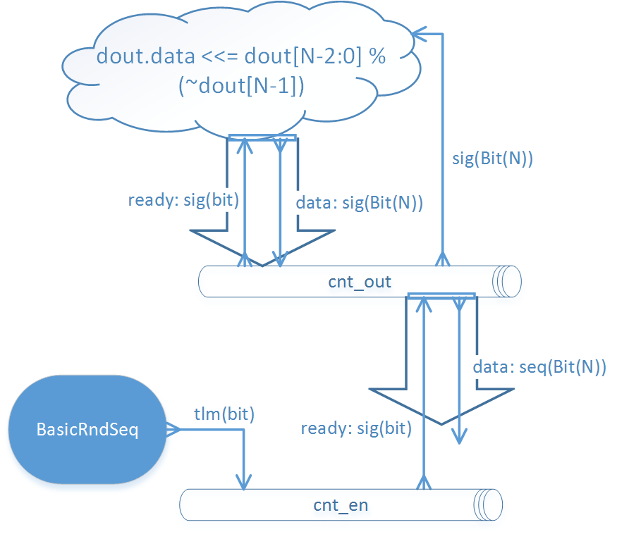
The dataflow of Johnson counter testbench, with ready and data subinterfaces.
This results in BasicRndSeq module output randomly starting and stopping our counter module. The VCD waveform is given below:
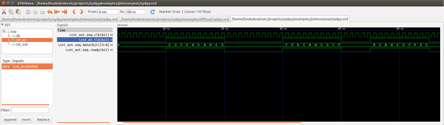
The VCD waveform of Johnson counter testbench viewed by GTKWave.
Please note also how the parameter cnt_n is set using the configuration dictionary. The parameters of arbitrary modules can be set via hierarchical paths using the following pattern:
'absolute_path.parameter_name' : value
The top module always gets the name: ‘top’, making his absolute path: ‘/top’. Submodules can be given names via inst function and the name parameter, for an example:
self.inst(Johnson, name='Counter1', clk='clk', dout='cnt_out', N=cnt_n)
If the name parameter is omitted, the submodule gets the name of its module class. In our example, the Johnson counter submodule will get the name: ‘Johnson’, and the absolute path: ‘/top/Johnson’.
Wildcards * and ? can also be used in configurations. So, if we had multiple counters with parameter N, all named after pattern ‘Counterx’ (where x is an arbitrary single digit), but scattered over the hierarchy, we could set their parameters with single configuration entry:
'*/Counter?.N' : value
CRC-32 generator example
A more complex example shows how to implement CRC-32 (32-bit Cyclic Redundancy Check) generator, that is used in Ethernet protocol for an example. Whole example can be found in the examples/crc32/crc32.py.
class Crc32(Module):
    @arch_def
    def rtl(self, clk: sig(bit), crc_in: seq(bit8), crc_out: seq(bit32).master):

        crc_table = setup_crc_table()

        crc_in.clk <<= clk

        crc_states = Enum('idle', 'conv')
        crc_state = self.seq(crc_states, master='crc_state', init='idle', clk=clk)

        crc_calc = self.seq(bit32, 'crc_calc', init=0xffffffff, clk=clk)
        crc_calc.s_con(**subintfs(crc_in, ['valid', 'last']))

        @always_comb(self)
        def crc_state_proc():
            if crc_in.last:
                crc_state.next = 'idle'
            elif crc_in.valid:
                crc_state.next = 'conv'

        @always_comb(self)
        def crc_calc_proc():
            if crc_in.valid:
                if crc_state == 'idle':
                    crc_calc.data.next = (0xffffffff >> 8) ^ crc_table[(0xffffffff ^ crc_in.data) & 0xFF];
                else:
                    crc_calc.data.next = (crc_calc >> 8) ^ crc_table[(crc_calc ^ crc_in.data) & 0xFF]

        crc_out.s_con(valid = crc_calc.last,
                      data  = ~crc_calc.data,
                      )
        crc_out.clk <<= clk
Let’s notice several new things:
- Enum class can be used generate an enumeration data type.
- The subintfs helper function can be used to enumerate the subinterfaces of an interface to a dictionary.
- The s_con interface helper function can be used to connect several subinterfaces with one function call.
The setup_crc_table function is not listed here (since it is not important for this discussion), but can be found in the examples/crc32/crc32.py module.
SyDPy allows for several architectures to be defined for a single module. Let’s add an architecture implementation on higher abstraction level:
@arch
def tlm(self, crc_in: tlm(Array(bit8)).slave, crc_out: tlm(bit32).master):
    @always_acquire(self, crc_in)
    def proc(val):
        crc = 0
        for b in val:
            crc = zlib.crc32(bytes([int(b)]), crc)

        crc_out.blk_next = crc
This architecture is just a wrapper around the Python zlib library crc32 function. Please notice that this architecture deals with whole transactions, i.e. whole array of bytes for which CRC is to be generated.
Verification environment for CRC32 generator
The following code can be used to simulate the CRC32 generator module we implemented:
class TestCrc32(Module):
    @arch_def
    def dflt(self):
        self.inst(Clocking, clk_o='clk', period=10)

        self.inst(Crc32,
                    clk     = 'clk',
                    crc_in  = 'crc_data',
                    crc_out = 'crc',

                    arch=['rtl', 'tlm'],
                    scrbrd=(Scoreboard, {'intfs': {'dut_i': tlm(bit32).slave, 'ref_i': tlm(bit32).slave}})
                  )

        self.inst(BasicRndSeq, seq_o='crc_data', delay=(0, 150), intfs={'seq_o' : tlm(Array(bit8, 10)).master})

conf = {
        'sys.top'           : TestCrc32,
        'sys.extensions'    : [VCDTracer],
        }

for t in UnitTest([(conf, 'crc32')], verbose=True):
    assert bool(t) == True
Let’s notice several new things:
- The arch parameter of the inst function can be used to tell which architectures should be instantiated. If a list of architecture names is passed to inst, only the first one is connected completely with the parent module. The others get their inputs connected correctly, however their outputs are assigned to different channels (since we would have multiple interfaces writing to same channels).
- The scrbrd parameter can be used to pass a Scoreboard module to the inst function. This Scoreboard module can be used to perform automatic equality check between the output generated by different architectures.
- The BasicRndSeq generates whole transaction at the time. It is assigned Array(bit8, 10) data type, meaning that it should generate an array at most 10 bytes long.
- The rtl architecture reads data from the channel written by BasicRndSeq one byte per clock cycle. The serialization of the byte array is performed automatically by SyDPy.
Notice also how same testbench can simultaneously drive two architectures at different levels of abstraction, which have different interfaces to the same channel.
In order to check the scoreboarding results, the UnitTest class can be used. UnitTest is passed a list of configuration to run a simulation on. After each simulation run, UnitTest searches for all scoreboard results within the design and creates the result objects. The result objects of the UnitTest can be accessed by iterating over UnitTest object (as shown in code above). When tested with the bool function, the result object returns True if all tests of the scoreboard passed and False otherwise. In our example, the scoreboard will check every transaction generated by Crc32 module’s two architectures and compare them. So the assertion in the code above will only be satisfied if both architectures (rtl and tlm) always yield equal transactions.
An example of simulation run VCD output is given below:
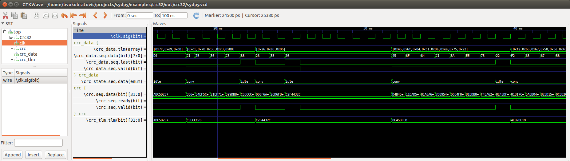
The VCD waveform of CRC32 testbench viewed by GTKWave.
The crc_tlm channel was created ad-hoc by the Scoreboard to receive the transactions generated by tlm architecture (since we cannot have both rtl and tlm outputting to the same crc channel).
We can check on the waveform too that rtl and tlm output the same values. The tlm architectures operation is not affected by the clock and yields the result to crc_tlm.tlm signal as soon as new data arrive from crc_data.tlm signal (for example at 18ns, 22.5ns, 31.5ns...). However, the rtl architecture is implemented at RTL level, and operates sequentialy synchronous to the clock. One clock cycle is needed for every byte in the crc_data.tlm array. The rtl architecture announces the result is ready by setting the crc.seq.valid signal to high and outputting the result to crc.seq.data (for example at 21.5ns, 24.5ns, 38.5ns...).